Single-Tone Music Card
The end result would be a music player that produces at single tones with correspondingly flashing LEDs.
Preliminaries
I began by familiarizing myself with PIC16F627A by going through its documentation. I mainly focused on what the microcontroller is capable of and eventually settled on PWM to be the main tool. The project has not been ideated at this point. I decided that it would be easier to determine what tool I'd like to use beforehand as the main objective is simply to learn about microcontrollers.
Pulse Width Modulation (PWM) is a technique that generates signal with variable with pulses. Essentially, it is a digital signal that turns on & off at a specifed interval to emulate that of analog. With a use of a transistor, this technique can be used to modify a DC voltage.
Active Piezoelectric Buzzer produces sound by using piezoelectric materials that deforms when alternating voltage is applied across them. As the material vibrates rapidly, a sound is produced. Active peizo buzzer has a build-in oscilitor, so it is able to receive DC voltage.
Prototype
Now that I can recognize what pins of the microcontroller I can use, a rough schematic can be sketched out.
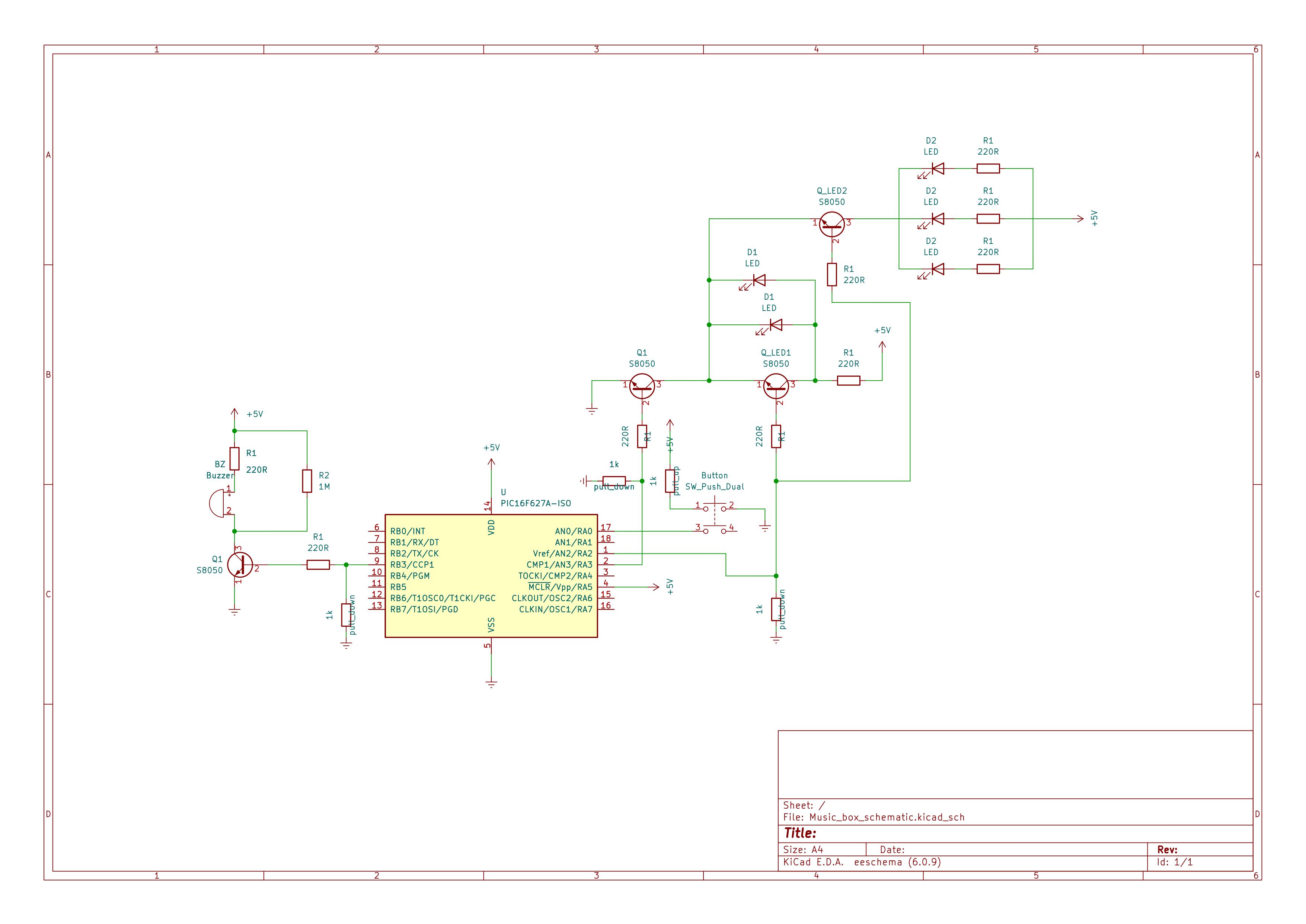
Flashing LEDS: Three transistors are used. One will be used as a switch to enable/disable the flashing LEDs function as we would only like them to be flashing while the music is playing. While no sound is being produced, the LEDs will be entirely turned off. The other two are used to 'flash' the LEDs alternately alongside each shift in the produced tone.
Piezoelectric Buzzer: The buzzer is connected to a transistor that is controlled by the generated PWM signal from the microcontroller. The pitch of produced music notes corresponds to the variable voltage across the buzzer. Therefore, the pitch can be shifted accordingly by modifying the period of the PWM signal. Each song (a sequence of frequencies with varying time interval) will have to be incorporated within the microcontroller.
Code for the microcontroller can be found here as "Project_main.c".
Demo
Conversion to PCB
In order to wrap up the project neatly, I have created a pcb with the designed circuit. Below is the finalized circuit which was sent to a fabricator. Not many major changes were made to the rough schematic. (Only the transistors were replaced by a quad transistor array.)
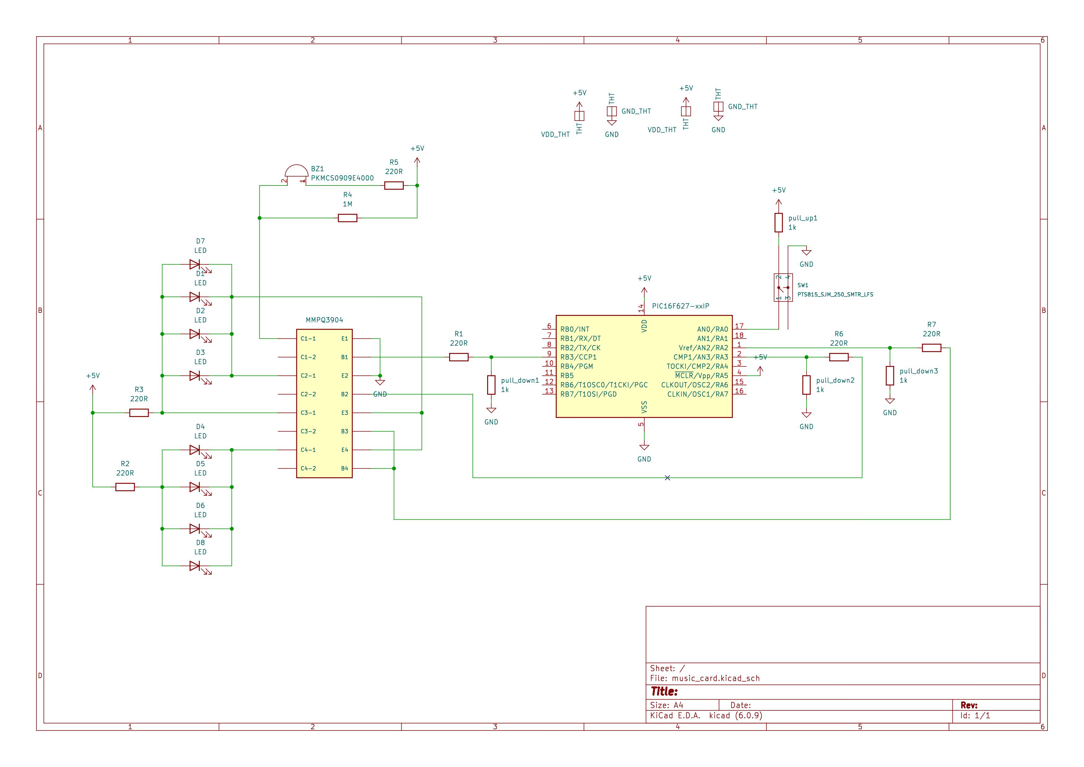
The gerber files can be found here.
Final Demo
*A few LEDs appeared to have been short-circuited due to soldering error. No voltage difference is being read across the component.*